The most time consuming part of the swap. I was somewhat reluctant
about doing this swap because I was afraid of the daunting task
of the wiring. However, once I got into it it was fairly straightforward,
but very time consuming. I had no previous experience doing anything
like this before. I do have an electrical engineering background,
but nothing automotive. (If you are new to this as well, I suggest
reading up on a set of Toyota Technical manuals that are available
at Autoshop101.com. Great
way to learn about Toyota's systems.)
I took my time with the wiring, basically working on it throughout
the mechanical part of the swap. Since it doesn't involve any real
physical dirty work, I worked on it when I wanted to take a break
from those sort of things. Plus once I got the wiring harness mapped
out on paper, I could do all the work inside the AC'd house.
-
The first step is to label each connector as you remove it
from the engine.
-
Once you get the harness out of the engine, start taking notes
on each connector. Include the orientation of the pinout and
the wire colors. Make sure to keep some space between the difference
pins, as you will be making more notes here shortly.
-
Next, start taking apart the harness, removing all the tape
and wire loom. Make sure to keep the harness organized and untangled,
as well as in it's original layout. Once you have the original
loom & tape off of a section, loop a piece of electrical
tape around the wires. A loop of tape every 12-18 inches will
keep everything from getting tangled. Also, make sure to keep
the wire loom so that you can reuse it once you get the loom
completed.
-
When this is done, begin mapping out each and every wire. This
is where most of the time is spent, but it is very important
in getting to know the wiring harness. It also makes removing
unneeded accessories a breeze. If you did not get a clip or
half cut, this is going to make this sorta difficult, as there
are quite a few wires that will just terminate at the body harness
connectors. Most of these are the instrument cluster, AC, ABS,
and ignition switch signals. A couple of them are for the idle-up
circuitry as well. If you do have a clip, trace these pins at
the body harness connectors if you can't figure out which signals
they are by where they terminate on the engine harness. There's
no need to torture yourself and map out the entire body harness.
Unless you really want to. Though it is nice having the body
harness stripped so that you can use it for spare wire and pins.
-
Now, start removing these unneeded circuits. These circuits
won't have all their wires on exclusive connectors. So you will
need to remove some pins/wires from other needed connectors.
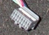
To do this, you need something with a very tiny point. I just
used a safety pin the whole time. On the late style Toyota connectors,
there is usually a lock on them that you need to raise. See
the white rectangular area on the connector below? Pry up on
the two indented spaces with the safety pin and the lock should
raise up. Do NOT attempt to remove the lock entirely from the
connector. Not only is it unnecessary, but you could also destroy
the lock.
Once it is in the up position you can remove the pins by releasing
the tab that is holding the individual pins inside. Look at
the front of the connector and you should easily see the tab
that you need to push down. While pushing down with the safety
pin, pull the wire out from the back of the connector. For the
older style Toyota connectors (what is on the MKI MR2) this
is the only thing holding the pins inside the connectors. There
is no lock.

The circuits I removed from the 20V engine harness were the
ABS, headlights, radiator fans, horns, and AC. Now's the time
to decide whether or not you will want to use AC.
-
After that is done, set the 20V harness aside and begin work
on the MR2 harness. I also removed the body harness from the
MR2, which made it easier to trace wires back into the fuse
box (the engine fuse box is on the body harness of the MR2,
engine harness of the 20V). I also needed to run more wires
to the MR2s body harness for the Blacktop, more on that later.
-
No need to label every connector on the MR2. Only the main
ones that you will reuse, the trunk connector, the grey connectors
in the engine bay, and the body harness connectors that interface
to the MR2's interior harness. Also, are you going to use the
MR2's engine bay fan? If so, make sure to label those.
-
Once removed, begin stripping the old tape and loom from the
MR2 harnesses. Try your best to keep the firewall grommets intact.
I ended up slicing them down the middle to remove them from
the harness. This worked farily well.
-
If you are going to use the engine bay fan, remove that circuit.
It's very straightforward. Now, start mapping out the wires
that interface between the body and engine harness. Use the
wiring diagrams in the BGB and/or Haynes manual to help. There
may be some discrepancies within the documentation so be sure
to check the circuits by hand just in case.
-
By now, you should understand what all you need to do to join
the 20V engine harness to the MR2 body harness. Here's a diagram
that will hopefully help you out, that I put together after
the swap (click on it for larger pic). This is the Blacktop
wiring diagram drawn in the form of Toyota's MR2 diagrams. The
red lines indicate that it is part of the engine harness, and
the black is the MR2's body harness. So...wherever black meets
red is a signal that you will need to pull to your connector
interface.

- The Silvertop harness will be slightly different, at least
with the COR. The Alternator Sensing fuse is optional. You could
just tie this to B if you wish.
- Notice how I wired the engine bay fan as well. This way it's
on whenever the ignition is in the ON position. You could wire
it up like the 16V MR2 with the temp sensor and the computer
if you wish. Just takes a couple more wires and mounting of
the sensor in the engine bay.
However, these are not the only signals needed to complete the
interface. There are a few other wires on the body harnesses needed
for the ECU. Below is a diagram of all the ECU signals. Those
in blue indicate signals contained the above wire diagram. TC1
and TC2 are the two trunck connectors I used to complete the interface.
So those in black that go to TC1 and TC2 will need to be in the
interface as well.

I used the original trunk connector that was on the MR2 harness
and an additional connector I grabbed from the 20V body-engine
harness interface. I was able to eliminate both engine bay grey
connectors on the original MR2 body harness which makes things
a little neater in the engine bay. It may be possible to use only
one connector, especially if you are doing a silvertop swap.
New Connector Diagrams
Here are pin description tables of the 2 connectors I used. By
no means is this the only way to do this, it just is here to give
you an idea of the signals you will need to run:
Update (Feb 14, 2008): I changed the first connector
around a bit to keep this with what I'm actually currently using.
When I shortened the harnesses in the trunk a year or so ago,
I moved the 4 ELS signals to the second connector to reduce the
number of contacts in this main connector. It was becoming too
hard to detach/reattach the connector. I've also added the 2nd
connector diagram as well as the stock 16V connector diagrams.
New 20V Trunk Connector #1:
|
Body Harness (Male)
Side |
Engine Harness (Female)
Side |
1 |
G/W |
Check Engine Light to Dash |
R/Y |
Check Engine Light from ECU |
2 |
Y/Blk |
Oil Pressure to Driver's seat connector |
W |
Oil Pressure Sensor |
3 |
R/W |
Batt from EFI Fuse |
R/W |
Batt to ECU |
4 |
NC |
|
NC |
|
| |
5 |
Blk |
Starter Relay |
Blk |
Terminal 50 on Starter |
6 |
Y/G |
Water Temp Gauge to Driver's seat connector |
Y/G |
Water Temp Sensor |
7 |
Blk |
+B EFI Relay |
Blk |
+B COR, ECU, O2 Sensor, etc |
8 |
Blk/Y |
10A Engine Fuse |
R/Blu |
Alternator IG signal |
9 |
NC |
|
NC |
|
| |
10 |
Purp/W |
Speed Sensor to Driver's seat connector |
Purp/W |
ECU Speed Sensor input |
11 |
R/Blk |
L&R Reverse Lights |
R/Blk |
Reverse Switch on Tranny |
12 |
Blk/R |
Power from Ignition Main Relay |
Blk/W |
Ignitor/Coil & Injectors |
13 |
|
Cooling Fan Relay coil side |
LG/Blk |
CF from ECU |
14 |
NC |
|
NC |
|
| |
15 |
Blk |
IG- to Tachometer to Driver's seat connector |
Blk |
IG- from Ignitor/Coil & Diagnosis |
16 |
W |
Alt 'S' 5A fuse (added to fuse/relay box) |
W |
Alt 'S' Signal |
17 |
Y |
5A Charge 'L' Signal from Alternator |
Y |
'L' Signal from Alternator |
18 |
Blu |
Fuel Pump |
Blu/Blk |
Circuit Opening Relay & Diagnosis |
19 |
NC |
|
NC |
|
| |
20 |
Blk/G |
Engine Bay Fan |
Blk/G |
Engine Bay Fan |
21 |
Blu/W |
Engine Bay Fan |
Blu/W |
Engine Bay Fan |
22 |
Blu/Blk |
Engine Bay Fan |
Blu/Blk |
Engine Bay Fan |
Here's just another way at looking at the connector pin descriptions
(click to zoom in):

Blue = Body Harness
side
Red
= Engine Harness side
* = there's
2 ways to do this. I wired the engine bay fan to be on whenever
the ignition is on. If you would like to keep the original wiring
with the cooling fan computer and the temp sensor, just use the
2 empty spaces for the other 2 wires (Blk/G & Blu/W) in the
circuit.
New 20V Trunk Connector #2:
The second connector contains the STA signal, a ground, the idle-up
signals, and some optional things I wired in (air/fuel meter and
a VVT light in my dash (which i need to fix, cause it's still
not wired right in my dash)).
|
Body Harness (Male)
Side |
Engine Harness (Female)
Side |
1 |
NC |
|
NC |
|
2 |
W/Blk |
|
W/Blk |
|
| |
3 |
Blu/R |
Cooling Fan Relay switch side |
W/Blu |
ELS1 to ECU |
4 |
Blu |
Blower Relay |
Blu |
ELS2 to ECU |
5 |
Blk/W |
Starter Relay |
Blk/W |
ECU STA |
6 |
NC |
|
NC |
|
7 |
-- |
A/F Meter Ground |
-- |
O2 Sensor Ground |
| |
8 |
G |
Taillight Relay |
G |
ELS3 to ECU |
9 |
Blk |
Defog Switch |
Blk |
ELS4 to ECU |
10 |
R |
Dash |
R |
ECU VVT |
11 |
NC |
|
NC |
|
12 |
-- |
A/F Meter Signal |
-- |
O2 Sensor Signal |
Blue = Body Harness
side
Red
= Engine Harness side
Old 16V Connectors
I've gotten some emails in the past to document the stock
16V connectors. These vary by year, but here's what I had on my
'85:
Stock 16V 4-pin Grey Connector in the engine
bay:
Battery +
Various Big
Fuses
Battery, Alt, Starter
Black |
Battery +
Various Big
Fuses
Battery, Alt, Starter
W |
Engine Bay Fan Power
Fan Relay
Engine Bay Fan
Blue/Black |
Term50
Starter Relay
Terminal 50 on Starter
Black/W |
- The 2 Battery+ were connected together on the other side of
the connector and were part of the alternator & starter
wiring direct from the battery. This is taken care of by the
battery relocation wiring that I did, where I wired directly
from the battery to the starter and alternator.
- The other 2 were moved to the trunk connector
Stock 16V 12-pin Grey Connector in engine
bay:
Engine Bay Fan
NC
Engine Bay Fan
Blue/W |
-- |
Clutch Start Switch
Driver's side kick panel
Back to starter relay pin
Black/W
|
AC Clutch
AC Clutch Fuse
ECU
Black/W
|
-- |
-- |
| -- |
-- |
Starter Relay
Starter Relay
Back to clutch start switch pin
Black
|
| -- |
CEL
Gauge cluster
ECU
G/W
|
-- |

)
)
)
)